|
When Keith Duckworth’s DFV engine burst onto the Grand Prix scene in 1967 it represented the cutting edge of racing engine technology as it was at that time, with compact cylinder heads having four valves per cylinder providing excellent flow dynamics and good combustion. It was also innovative in its unified packaging and use of modern manufacturing techniques rather than the piecemeal one-off methods that had formerly been more usual.
The DFV reigned in F1 until 1983 when the looming threat from turbocharged engines at last became reality. When the performance excesses of the turbos eventually caused them to be regulated out of F1 the DFV’s descendents, the DFR and then the HB, were competitive yet somehow during the passage of time engine speeds around 1989 had not risen very much above the 11,000 r.p.m. of a late DFV.
Certainly there had been F1 engines that could run safely at up to 13,000 r.p.m., notably Renault’s turbo V6 with its pneumatically sprung valve gear, but all teams were finding that fuel consumption became excessive at these high speeds and any power gained was therefore only viable for qualifying and brief bursts in a race.
For years there had been a well entrenched belief that there was not much point in pursuing engine speeds much above 12,000 revs because there would not be sufficient time for combustion to proceed to finality. Rising friction losses and the problems of forming a combustible mixture in the brief time available both tended to reinforce the hypothesis. Logically there must be some point at which engine speed does reach a practical limit but had it been reached or was it just getting harder to make progress?

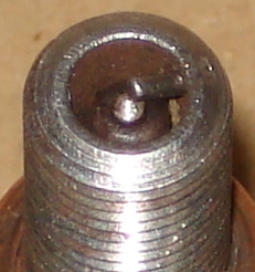
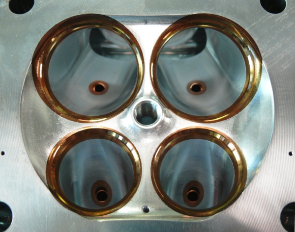
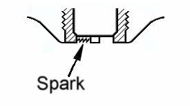
Fig. 1. Classic racing spark plug tip The DFV appeared to have approached the pinnacle of combustion chamber design for high performance yet the standard ignition timing of 35 degrees advance at 7000 r.p.m. was about the same as for a Manx Norton 20 years earlier. Even the design of racing spark plugs had not changed much and still featured a depressed central electrode and side entry ground pin to avoid the danger of pre-ignition (Fig.1). There has always been a need for the ignition timing to be advanced with rising speed but eventually this becomes unproductive if the spark is delivered to a charge that is not adequately compressed and has not reached the later stages of turbulence. The limiting point seems to be about 60 degrees before TDC and further advance can fail to bring forward the point of maximum combustion pressure. There had been engines that could operate effectively at speeds of around 20,000 r.p.m. in model aircraft and in small capacity motorcycle racing but they tended to be regarded as freaks which exploited the benefits of scale effect and negligible flame travel inside diminutive cylinders. The state of the art by 2010 finds specialist model engines reaching 40,000 r.p.m. which means combustion must be accomplished within about 0.00015 of a second. This is about as close to instantaneous as could be imagined so is more akin to detonation than the progressive burning process we have to aim for to control stresses in larger engines. Of course human ingenuity eventually finds a way of overcoming most perceived barriers and the combination of clever design and improved materials could alleviate friction losses, whilst higher injection pressures and finer atomisation could improve mixture formation. The most stubborn obstacle was how to speed up combustion and in particular the torpid early stage known as ignition lag lasting for about 0.5 to 1.0 millisecond after the spark strikes until combustion becomes discernable. If higher engine speeds were ever going to be possible with reasonable sized cylinders then it would be necessary to not only considerably reduce ignition lag but also to speed up the rest of the process. By 2006 F1 engines were reaching 20,000 r.p.m. at which speed a lag period lasting 0.5 of a millisecond would take up 60 degrees of crank rotation, so obviously a solution to the problem had been found. All the current V8 engines in F1 owe something to the DFV in their design but so much cash is involved in modern racing technology that very little detailed information is made publicly available these days. Fortunately Toyota, having withdrawn from F1, realised that there was much to be proud of in their RVX-09 engine and decided that they could now obtain good publicity for their technical expertise by exposing its internal features. We therefore have a useful yardstick with which to judge the advances of the modern F1 engine with respect to the original DFV. The table below shows the essential figures.  It is well known that if b.m.e.p. can be maintained then any increase of r.p.m. will produce a proportionate increase of power output. What is truly remarkable is that the Toyota does not just maintain b.m.e.p., it actually increases it by 13% whilst virtually doubling the r.p.m. at which it is achieved. The specific power output is consequently increased by no less than 124% over the legendary DFV!  Fig. 2. Toyota Combustion Chamber showing projecting spark plug location. Courtesy of Toyota Obviously reduction of friction losses is critical for this sort of advance but ultimately the engine has to be able to consume proportionately greater amounts of air and fuel to beat the DFV by such a margin. The larger bore of the Toyota (96.8 mm) compared to the DFV (85.67 mm) allowed valve area to be increased by 41% and probably the port area is greater by about 45%. Inlet valve lift, however, at 15.4 mm is almost 50% more than the 10.4 mm of the DFV, although the cam opening duration is thought to be less by about 20 degrees or so. Gas velocities through the ports are undoubtedly significantly higher but a sizable proportion of the improved cylinder charging will be from better exploitation of pulse tuning in both the induction and exhaust systems. The DFV originally had rather bland four-into-two-into-one exhaust systems on each bank but these were soon replaced by more effective four-into-one systems, which the Toyota also has – although in more advanced form. Effective cylinder charging is dominated by correctly synchronised changes of density rather than simple flow technology.  Fig. 3. DFV (top) and the Toyota piston crown showing the raised squish zones of the latter. Courtesy of Toyota The compression ratio of the DFV was 11:1 at a time when road cars were rarely more than 9:1 even with 100 octane (RON) fuel. These days 11:1 would not be unusual for a road car using 95 octane fuel so it is hardly surprising that the Toyota compression ratio is 13.6:1 for the mandatory 102 octane fuel. In fact at the sort of speeds these modern F1 engines run to there just isn’t time for detonation to be a problem although pre-ignition could still be a threat in the wrong circumstances. That Toyota, and presumably their contemporaries, can actually achieve a compression ratio so high in cylinders of such an exaggerated bore/stroke ratio is partly due to the tighter valve included angle of 21.2 degrees (compared to the 32 degrees of the DFV) and each pair being splayed apart by 3.2 degrees. The simple pentrooof combustion chamber of the DFV has also been superseded by projecting the spark plug right into the centre of the chamber (Fig. 2). Some engines also have raised diffuser-like ridges between the valves but the demand for high compression has to be balanced with the needs of charge movement and combustion. The almost flat piston crown of the DFV with modest angled cut-outs for valve clearance has given way to a complex shape with raised squish zones around all the valves and even under the spark plug itself (Fig. 3). Any tumble swirl produced by the high gas speeds is disrupted into intense turbulence as the piston rises and then the charge is finally driven inwards from the peripheral squish zones and outwards from under the spark plug, the spark having long since done its work. Of course squish works in reverse as the piston starts to descend so the expanding charge gets a final stir to help finish the burning process.  Fig. 4. Surface discharge spark plug. The spark plug technology itself has changed dramatically from the traditional racing plug and OPUS ignition used by the DFV. A modern F1 spark plug has no ground electrode because the discharge takes place across the surface of the insulator material where it is immune from the tempestuous charge motion around it (Fig. 4). The spark itself is generated by capacitor discharge and so is very brief, about a tenth of a millisecond, or about 10 degrees of crank rotation, with an energy level of about 50 mJ, which is considerably more than is considered adequate to fire a standard road engine. Such a fearsome spark into the centre of violent charge motion spreads flame so rapidly that the entire combustion process is completed in less than a millisecond, which indeed is absolutely necessary at 18,000 r.p.m. The DFV undoubtedly broke new ground at the time and was good enough to remain at the forefront of F1 for 17 years. Others have now refined its features to an extent that is truly remarkable. However, Keith Duckworth created the DFV in an age when there was no choice but to use fixed ignition timing and a fuel injection system that had no correction with respect to engine speed. He would have worked with paper, pencils and compasses, on a drawing board, using a slide rule for calculations because pocket calculators and personal computers only existed in science fiction. Perhaps we should not be too surprised at the subsequent progress with the vast array of technology available to modern engine designers.
Roger Bywater. |
| [ Main site ] |
Email aj6engineering@ntlworld.com, Tel/Fax:- 0044 (0)1625 573556 |